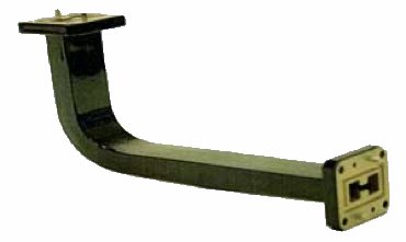
C = COVER STYLE |
G = GASKET STYLE |
– 1 =ALT. TAP & CLEAR |
– 2 =ALL TAPPED |
– 3 = ALL CLEAR |
|
3.5 – 40.0 GHz Performance Frequency
1.15 Typical VSWR (VSWR varies with design)
Numerous Flange Configurations available
Aluminum (6061) Waveguide Available
Corrosion protection with flat black finish
Advanced Microwave Components is proud to offer formed double ridge bends in a flash! Our waveguide sections are manufactured to our customer’s specifications.
All AMC components are produced with the highest quality available. We insure our quality through a ISO9001 / AS9100 certified quality system.
All parts are painted flat black and flanges are polished, unplated and iridited.
WR SIZE | FREQ: GHZ | MIN. inside radius | MIN. inside radius |
180 | 18.0 – 40.0 | 1.0 | 2.0 |
110 | 11.0 – 26.5 | 1.0 | 2.0 |
750 | 7.50 – 18.0 | 1.50 | 2.0 |
650 | 6.5 – 18.0 | 1.50 | 2.0 |
580 | 5.80 – 16.0 | 1.50 | 2.0 |
475 | 4.75 – 11.0 | 2.0 | 3.0 |
350 | 3.50 – 8.20 | 3.0 | 4.0 |
MODEL No. | W/G SIZE | FLNG
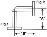
 | LEG DIM A+B | MATERIAL |
|---|---|---|---|---|
AMC-DREB | 580 | -C3/C3- | -3.0×3.0- | A |
The above referenced part number describes the following item: WRD580 “E” formed bend, cover flanges with clear holes, legs = 3.0″ each, made of aluminum. All bends are 90 degree, other degrees available upon request. Note: All AMC models include an iridite/corrosion protection treatment and are painted flat black. Flanges are unplated, iridited and polished. For other finishes, material, or paint color requirements, please specify.