A = AMC QUICK DISCONNECT (MALE) PATENT PROTECTED |
B = AMC QUICK DISCONNECT (FEMALE) PATENT PROTECTED |
C = MODIFIED CPR STYLE – GROOVE ONLY, NO CONTACTS (CLEAR HOLES) |
D = MODIFIED CPR STYLE – GROOVE ONLY, NO CONTACTS (ALL TAP HOLES) |
E = CPR STYLE FLAT (ALL TAP HOLES) |
F = CPR STYLE FLAT (CLEAR HOLES) |
G = CPR STYLE CONTACT GROOVED (CLEAR HOLES) |
H = CPR STYLE CONTACT GROOVED (ALL TAP HOLES) |
I = CMR (CLEAR HOLES) |
J = CMR (ALT/ TAP,/CLEAR HOLES) |
K = CMR (ALL TAP HOLES) |
L = UG COVER (CLEAR HOLES) |
M = UG COVER (ALL TAP HOLES) |
N = UG COVER GROOVED (ALL CLEAR HOLES) |
O = UG CHOKE (CLEAR HOLES) |
P = UG CHOKE (ALL TAP HOLES) |
Q = UG COVER GROOVED (ALL TAP HOLES) |
R = UBR |
S = PBR |
T = CBR |
U = UDR |
V = PDR |
W = CDR |
X = SPECIAL FLANGES (CUSTOMER TO SPECIFY) |
N = Type N Coax. Conn. – Female |
NM = Type N Coax, Conn. – Male |
S = Type SMA Coax. Conn.- Female |
SM = Type SMA Coax. Conn. – Male |
K = TYPE K/2.92 COAX. Female |
Frequency 1.7 – 18 GHz
1.15 Typical VSWR
SMA & Type N (Male or Female) Connectors Available
Mid-Band Nominal Coupling Values of 20-50 are standard.
Standard Material Copper (OFHC) or Aluminum (6061) Waveguide
10-20DB of Directivity is Typical
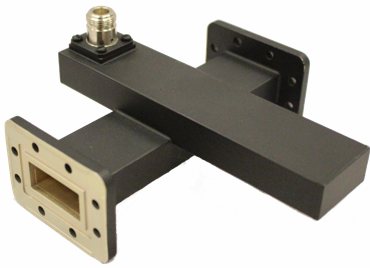
AMC offers a top of the line crossguide coupler that is used to sample the power traveling through a system. All AMC components are produced with the highest quality available.
We insure our quality through a ISO9001 / AS9100 certified quality system.
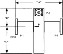
WR SIZE | FREQ: GHZ | DIM. A | DIM. B | DIM. C |
|---|---|---|---|---|
42 | 18.0 – 23.0 | 3..00 | 1.25 | 1.99 |
62 | 12.4 – 18.0 | 3.5 | 1.75 | 2.37 |
75 | 10.0 – 15.0 | 3.75 | 1.87 | 2.5 |
90 | 8.20 – 12.4 | 4 | 2 | 2.75 |
112 | 7.05 – 10.0 | 4.2 | 2.1 | 3 |
137 | 5.85 – 8.20 | 6 | 2.47 | 4 |
159 | 4.90 – 7.05 | 4 | 2.30 | 3.20 |
187 | 3.95 – 5.85 | 6.5 | 3.25 | 4.5 |
229 | 3.30 – 4.90 | 7 | 3.5 | 4.75 |
284 | 2.60 – 3.95 | 7.5 | 3.75 | 9.25 |
430 | 1.7 – 2.6 | 9 | 6.13 | 9.25 |
Specify Operating Frequency.
Return Loss (Main Arm) > 26dB.
Return Loss (2nd Arms) > 19dB.
Specify coupling direction (forward or reverse).
Specify if pressurization is required.
Note: All AMC-CGC models are made of Brass or Aluminum and include an iridite/ corrosion protection treatment. Flanges are unplated, iridited and polished. Finish is flat black. For other plating finishes, materials, or paint color requirements, please specify
MODELNUMBER | WAVEGUIDESIZE | FLANGE TYPEP1 + P2 | CONNECTORP3 | COUPLINGVALVE DB | MaterialA = Alum.B = Brass |
|---|---|---|---|---|---|
AMC-CGC | 75 | P/L | N | 40 | B |
The above part number describes the following: WR 75 crossguide coupler, with CHOKE FLANGE/COVER FLANGE on primary arm and a type “N” coax connection. The connector is on the secondary axis arm. The coupling value is 40dB. The last letter ‘B’ reflects the material Copper/Brass the other option is ‘A’ for Aluminum.